


Mobile Ship Loading Conveyor for Ports & Terminals | SANTO

Move bulk cargo from the receiving point to the vessel hold with a SANTO ship loading conveyor. Mobile configurations help terminals connect truck deliveries, loader-fed hoppers and shoreside transfer routes with the final loading position.
A successful installation matches 3 handling stages: receiving, transfer and vessel loading. Each stage must accommodate the cargo, target throughput and available quay space.
Explore SANTO’s mobile bulk material handling equipment and use the configurations below to identify a practical starting point for your port or terminal.
Choose a Bulk Ship Loading Configuration
Start with how cargo reaches the berth. The feeding method determines the receiving equipment, traffic layout and transfer route.
Truck-to-Ship Loading
Truck → Truck Unloader → Transfer Conveyor if Required → Ship Loader → Vessel
A truck unloader receives road-delivered cargo and feeds the downstream conveyors. This arrangement can remove an intermediate ground stockpile where the delivery schedule and loading operation support direct transfer.
Truck frequency matters. For an illustrative target of 500 t/h, trucks carrying 25 tonnes each must deliver:
500 ÷ 25 = 20 loaded trucks per hour
That equals one loaded truck every 3 minutes on average. This calculation describes the required supply rate, not a guaranteed unloading cycle. Vehicle positioning, tipping, departure and delivery gaps all affect the actual flow.
The SANTO Radial Truck Unloader provides one receiving option. Its RTU1215 model has a published 1,200 mm belt width, 15 m length and 700 t/h capacity. Confirm the material and downstream equipment before applying that rating to a project.
Loader-Fed Ship Loading
Wheel Loader → Hopper Feeder → Ship Loading Conveyor → Vessel
A wheel loader transfers nearby cargo into a receiving hopper. The feeder regulates output and supplies the downstream conveyor.
Match hopper capacity and receiving geometry to the loader’s bucket and operating cycle. Leave room for the loader to approach, discharge and return to the stockpile without crossing the conveyor route.
Stockyard-to-Ship Transfer
Stockyard Feeding Point → Transfer Conveyors → Ship Loader → Vessel
Transfer conveyors connect a storage or reclaim point with the berth. Plan each connection around the distance, elevation difference and receiving position.
The stockyard still needs a suitable reclaim method. Conveyors transport the incoming material; they do not automatically recover material from a ground stockpile.
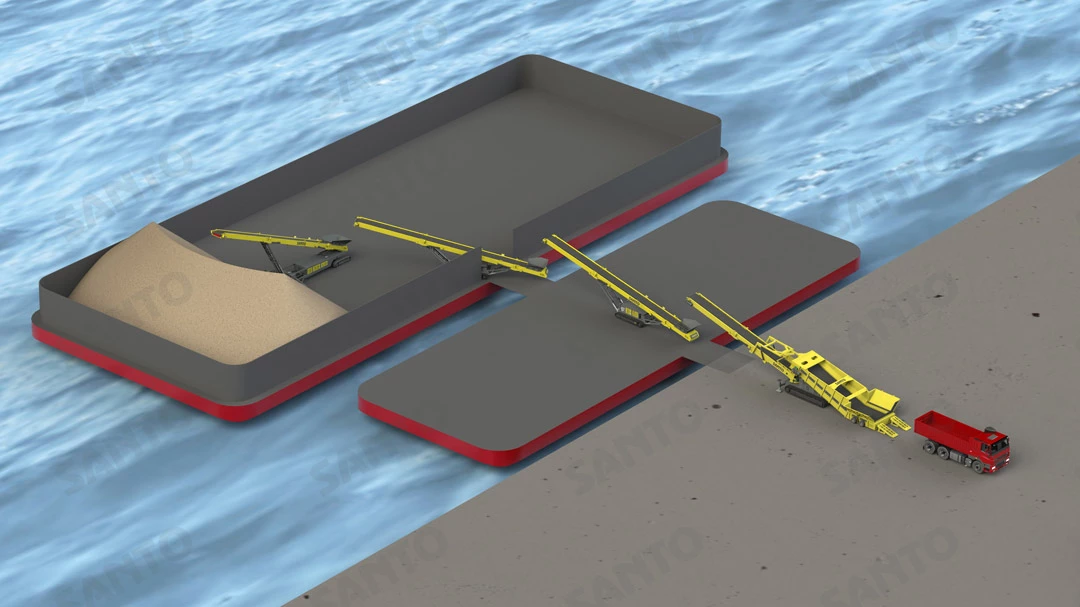
Truck to ship loading conveying solution diagram
Position the Discharge Point Around the Vessel
A mobile ship loader combines movement functions to reach the intended loading positions. Radial movement, telescopic reach and chassis relocation perform different tasks.
Use Radial Movement for Horizontal Coverage
Radial movement shifts the discharge point through an arc. Operators can use that movement to cover accessible areas within a hatch.
The pivot position and working radius determine the available coverage. Vessel structures, hatch geometry and quay obstructions can restrict the operating area.
Use Telescopic Reach to Adjust Outreach
Extension and retraction move the discharge point closer to or farther from the conveyor’s base. Elevation adjustment changes the boom angle.
Keep boom extension separate from loading-chute extension: the boom adjusts reach, while a suitable chute controls the final discharge path. Telestack’s technical documentation treats radial and telescopic positioning alongside separate chute options.
SANTO’s Radial Telescopic Stockpiler demonstrates its radial, telescopic and elevation-adjustment functions. Any proposed vessel-loading use requires a separate check of outreach, discharge height, structure and operating clearance.
Plan Relocation Between Loading Positions
A mobile chassis lets operators reposition equipment when the layout and operating procedure allow. The feeding connection, travel route and available working area must support that move.
ProStack identifies equipment relocation and berth flexibility as important considerations for mobile port conveyors. Mobility still requires a suitable site layout and ground conditions.
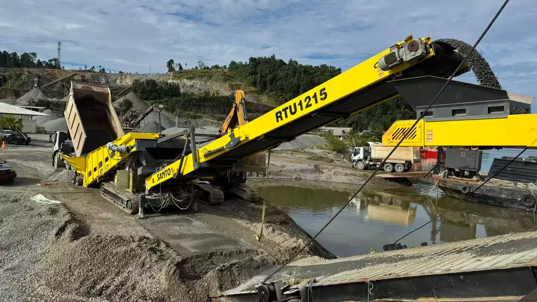
Truck to ship loading conveyor
Match the System to Your Cargo
Cargo properties influence receiving loads, belt selection, transfer geometry and discharge control. Provide measured material data rather than relying on the cargo name alone.
| Cargo group | Information to check |
|---|---|
| Coal and aggregates | Bulk density, maximum lump size, abrasion, moisture and dust characteristics |
| Ores and minerals | Density, impact loads, particle distribution and flow behaviour |
| Grain and biomass | Moisture, cleanliness, contamination sensitivity and material degradation |
Density changes the volume that a conveyor must carry. Consider these illustrative assumptions, rather than specifications for particular cargoes:
| Required mass flow | Assumed bulk density | Corresponding volume flow |
|---|---|---|
| 500 t/h | 0.8 t/m³ | 625 m³/h |
| 500 t/h | 1.6 t/m³ | 312.5 m³/h |
The lower-density material requires twice the volume flow at the same tonnage. Engineers must also assess belt speed, loading cross-section, inclination and transfer conditions.
Bruks Siwertell’s technical overview explains why different cargoes call for different conveying technologies and loading arrangements.
Connect Receiving Equipment with the Loading Position
Receiving machines, transfer conveyors and the final ship loader perform separate jobs. Select them as a connected system so one stage does not restrict the others.
SANTO publishes the following specifications for example receiving and feeding models:
| Model | Equipment role | Belt width | Length | Discharge height | Listed capacity |
|---|---|---|---|---|---|
| RTU1215 | Truck receiving | 1,200 mm | 15 m | 7.1 m | 700 t/h |
| FTS1015 | Hopper feeding | 1,000 mm | 15 m | 7.0 m | 500 t/h |
| FTS1215 | Hopper feeding | 1,200 mm | 15 m | 7.2 m | 700 t/h |
These figures describe individual machines. They do not establish the complete system’s vessel-loading rate or vessel compatibility.
For the transfer stage, the SANTO Grasshopper Conveyor offers adjustable discharge height and published length options from 20 to 45 m.
Check usable horizontal reach rather than adding machine lengths together. Conveyor inclination, overlap at transfer points and receiving positions affect the final layout. Confirm the selected transfer conveyor’s capacity independently.
Calculate Loading Time from the Whole Operation
A conveyor’s nominal rating does not describe the average rate across an entire loading window. Cargo supply, hatch changes, equipment repositioning and operational interruptions affect the result.
For illustration, assume a terminal must load 10,000 tonnes and the complete system sustains 500 t/h while conveying:
10,000 ÷ 500 = 20 hours of conveying
Now assume the operation conveys material during 70% of the elapsed loading window:
500 × 0.70 = 350 t/h average throughput
10,000 ÷ 350 ≈ 28.6 elapsed hours
The 70% figure is a planning assumption, not a SANTO performance claim or an industry benchmark. Use your terminal’s operating records to estimate a realistic value. Add berthing and other activities separately if they fall outside the loading window.
This calculation helps identify the actual constraint. A larger final conveyor may offer little benefit if truck deliveries or upstream feeding cannot maintain the required flow.
Specify the Conveyor Around Your Berth
Provide these 8 inputs when discussing a ship loading project:
| Project input | Details to provide |
|---|---|
| 1. Cargo properties | Material name, density in t/m³, maximum particle size in mm and moisture content |
| 2. Required throughput | Target operating rate in t/h and total cargo per vessel |
| 3. Vessel range | Beam, length, hatch dimensions, hatch spacing and onboard obstructions |
| 4. Vertical operating range | Relevant water levels, vessel freeboard and draft changes during loading |
| 5. Quay geometry | Feeding position, quay-to-vessel distance, working area and access routes |
| 6. Feeding method | Truck payloads and delivery frequency, loader details or existing conveyor data |
| 7. Power and operating conditions | Available supply, operating schedule and relocation requirements |
| 8. Cargo controls and maintenance | Dust-control needs, cleaning access and service space |
For loader-fed arrangements, compare your feeding cycle with the SANTO Feeder Track Stacker options. Confirm hopper geometry and output control alongside the headline capacity.
Include a berth sketch and vessel drawing. Mark the proposed feed point, conveyor route and loading positions so the engineering discussion starts with actual dimensions.
Address Dust and Cargo Distribution During Planning
Review every transfer point, not only the final discharge into the hold. Abrupt changes in flow direction and unnecessary fall height can increase dust and wear.
NIOSH’s transfer-point guidance recommends suitable chute geometry, smoother material flow and lower fall heights where practicable. Apply those principles to the cargo and equipment arrangement under review.
Equipment positioning must also fit the vessel’s loading plan. The IMO’s IMSBC Code addresses the safe stowage and shipment of solid bulk cargoes, including cargo-related hazards. Grain follows the separate International Grain Code. Conveyor selection does not replace the terminal and vessel teams’ cargo-specific planning.
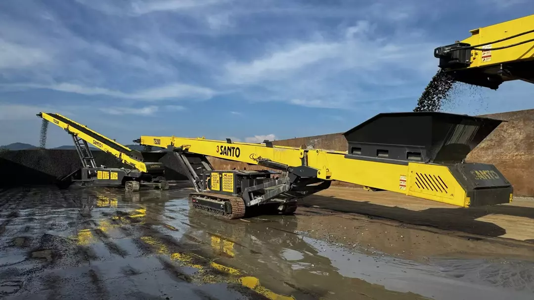
Mobile ship loading equipment
Ship Loading Conveyor FAQs
Can one mobile ship loader serve different vessels?
Yes, if its operating range covers the relevant vessels and berth conditions. Check outreach, discharge height, hatch positions and obstructions across the full vessel range.
Does a 700 t/h feeder provide a 700 t/h ship loading rate?
Not necessarily. Truck supply, transfer conveyors, the final ship loader and operating interruptions can limit throughput.
Can trucks supply the ship loading conveyor directly?
Yes, a truck unloader can receive truck-delivered cargo and feed the conveyor route. The layout may require one or more transfer conveyors between the receiving point and the ship loader.
How does a mobile system differ from a fixed installation?
A mobile system supports relocation between suitable working positions. A fixed installation serves an established material route and loading arrangement.
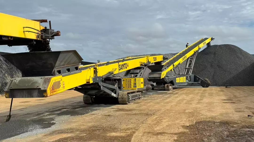
Mobile ship loading conveyor system
Discuss Your Port Ship Loading Project
Share your cargo properties, target loading rate, vessel drawings and berth layout with SANTO. Include your feeding method and available power so we can discuss receiving, transfer and loading requirements together.
If you already operate a conveyor system, provide its model details, discharge height and current throughput.
Contact SANTO to request a ship loading proposal.
External References: